Featured

TILT!Audio the new audio experience for your pinball

Welcome to TILT!Audio. TILT!Audio is an alternative sound system that offers much better sound experience than original sound hardware. It is build based on a Raspberry Pi and replaces the original sound board of your game.

TILT!Audio is the successor of RasPiSound so don’t get confused when in some forums or on my youtube channel it is called RasPiSound.

Wanna see it in action? Check out my youtube channel.

TILT!Audio is not a ready to use product that offers simple plug’n’play by simply replacing the old sound card. However you can easily build it for yourself (see Quick Start).

Order Now!

You do not even need to buy every little piece of hardware on your own, instead you can simply order DIY kits on my shop, that makes assembly very easy. For pinheads in the US you can also reach out to Charlie.

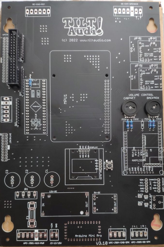
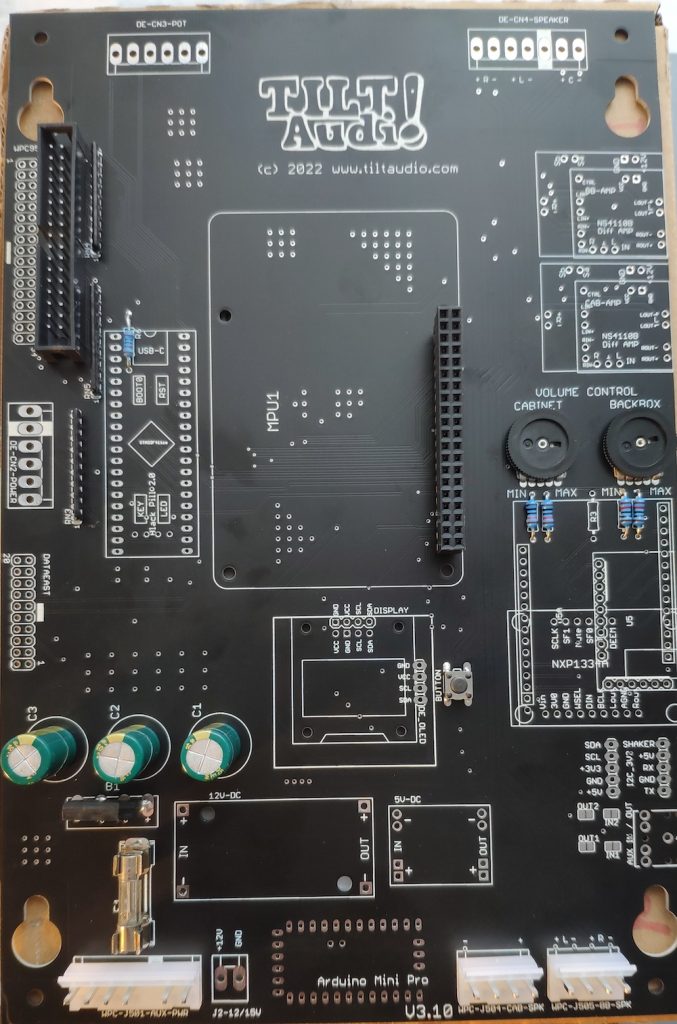
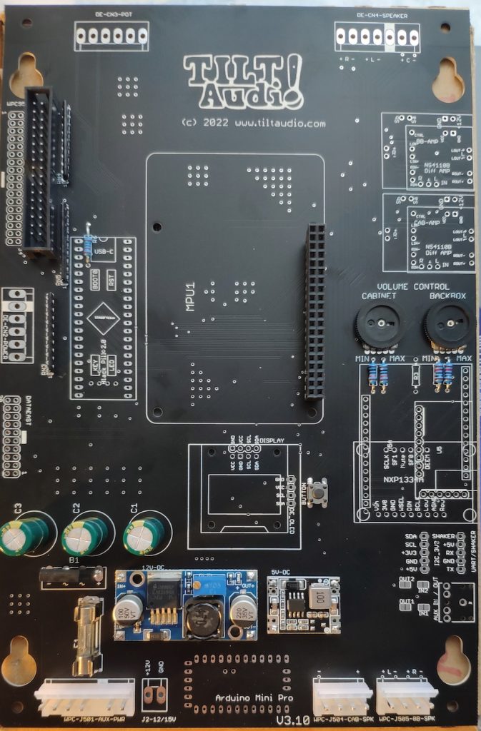
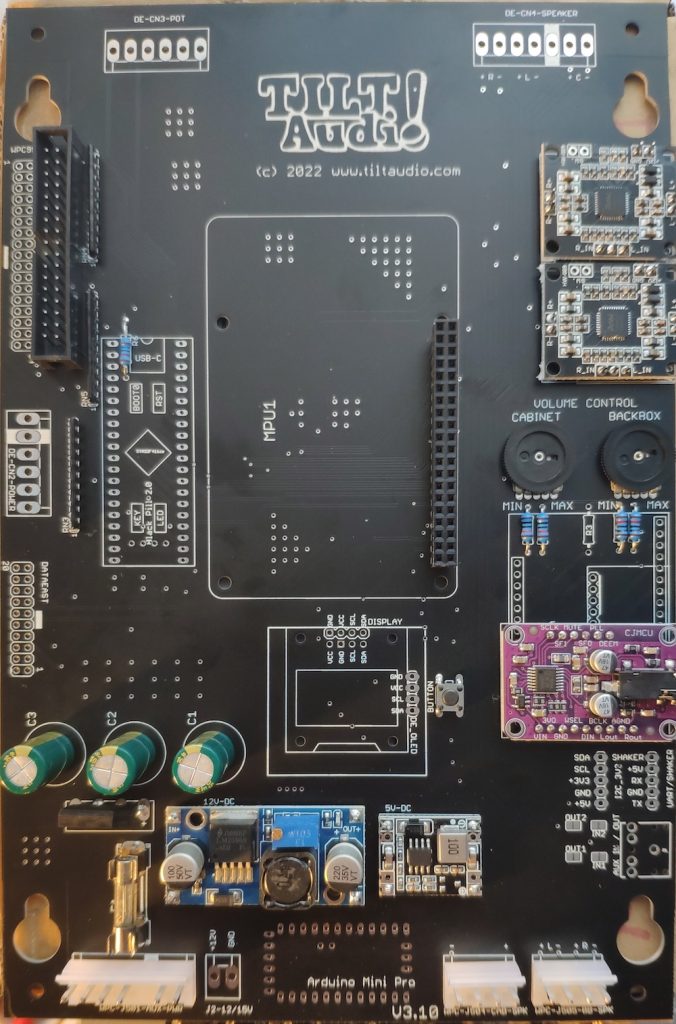
You can even take a look at the schematics and the latest pcb or export gerbers to build the board on your own. Everything you need is hosted on OSHWLab.

Board rev 3.10

The latest board has a slightly slimmer layout and the wider DCS like mounting holes can be removed. Also the mostly unused HF output filter for the amps were removed, so no more soldering bridges here.

This assembly post features a multi image step by step build up. So it should be easy to follow for everyone.

First solder the flat components like resistors, resistor networks, pots, idc connectors …

flat components first

Second add higher connector for the pi and molex connectors for the game, passive power supply parts: rectifier, caps, fuse …

higher connectors & passive comp. added

Then add the two DC DC converter modules

only power supply modules added

At this time you could (and maybe should) check the power supplies. So far no consumer is mounted, so connecting the J501 to the game (or left most & right most pin to a regulated power supply) should do no harm.

If all works well, you should have 12V on the amp power supply (upper right) and 5V e.g. on the connector right.

DAC module & amps added

Now with DAC module and amp modules added, you could do a test with the PI applied already. Everything should work, but of course only with sounds triggered from the webUI. This test could also be skipped.

Fully populated for wpc

Last step is added the stm (black pill) submodule and the OLED (optional, but recommended). Now with the PI attached, you should be ready to go.

Soldering time about 25 min.

Board rev 3.8 with Arduino

The new board rev comes with a dedicated place for a co-processor (arduino mini pro) to control various extension.

Fully assembled it looks like this

Fully assembled rev 3.8 board with arduino mini pro as co-processor and low noise amps
Arduino attached with 4 pins minimal, plus programming header

The arduino is connected with minimal 4 pins: Vcc, Gnd, SDA, SCL. Also the UART (RX,TX,Vcc,GND) on the left side has a header attached for programming. You can program the arduino “on board” but you either need to power the 5V from the machine and connect only TX, RX and Gnd or you also connect Vcc from the programming adapter (USB-to-Serial TTL) but then you need to disconnect the power from the board and also better remove the raspberry pi (board will be supplied by 5V from the adapter, which is okay for STM and DAC, but PI would be to much).