The new board rev comes with a dedicated place for a co-processor (arduino mini pro) to control various extension.
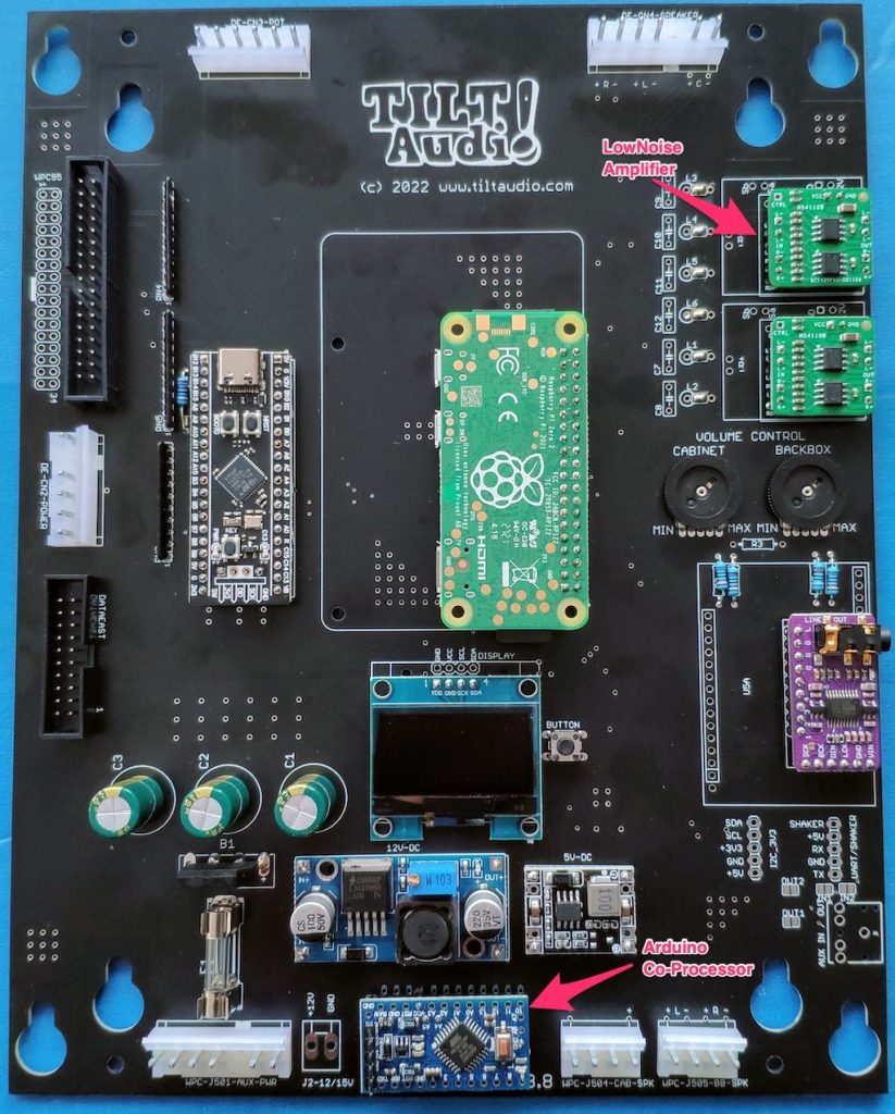
Fully assembled it looks like this
Fully assembled rev 3.8 board with arduino mini pro as co-processor and low noise amps
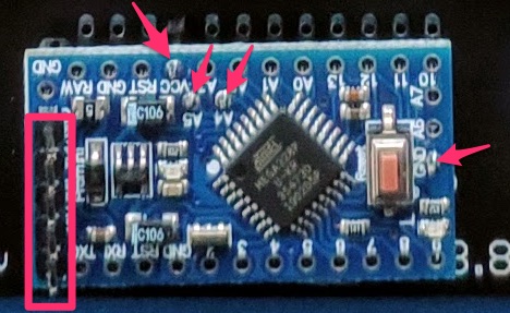
Arduino attached with 4 pins minimal, plus programming header
The arduino is connected with minimal 4 pins: Vcc, Gnd, SDA, SCL. Also the UART (RX,TX,Vcc,GND) on the left side has a header attached for programming. You can program the arduino “on board” but you either need to power the 5V from the machine and connect only TX, RX and Gnd or you also connect Vcc from the programming adapter (USB-to-Serial TTL) but then you need to disconnect the power from the board and also better remove the raspberry pi (board will be supplied by 5V from the adapter, which is okay for STM and DAC, but PI would be to much).
This adapter simply decodes parts of the 6809 address bus: A8 – A15. More fine grained decoding is not necessary as the peripheral address mapping is done by the upper 8 bit only.
So write access to 0b00111000???????? = 0x38?? will be recognized as a sound command.
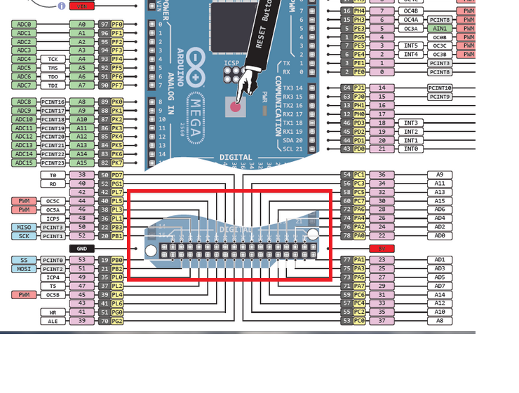
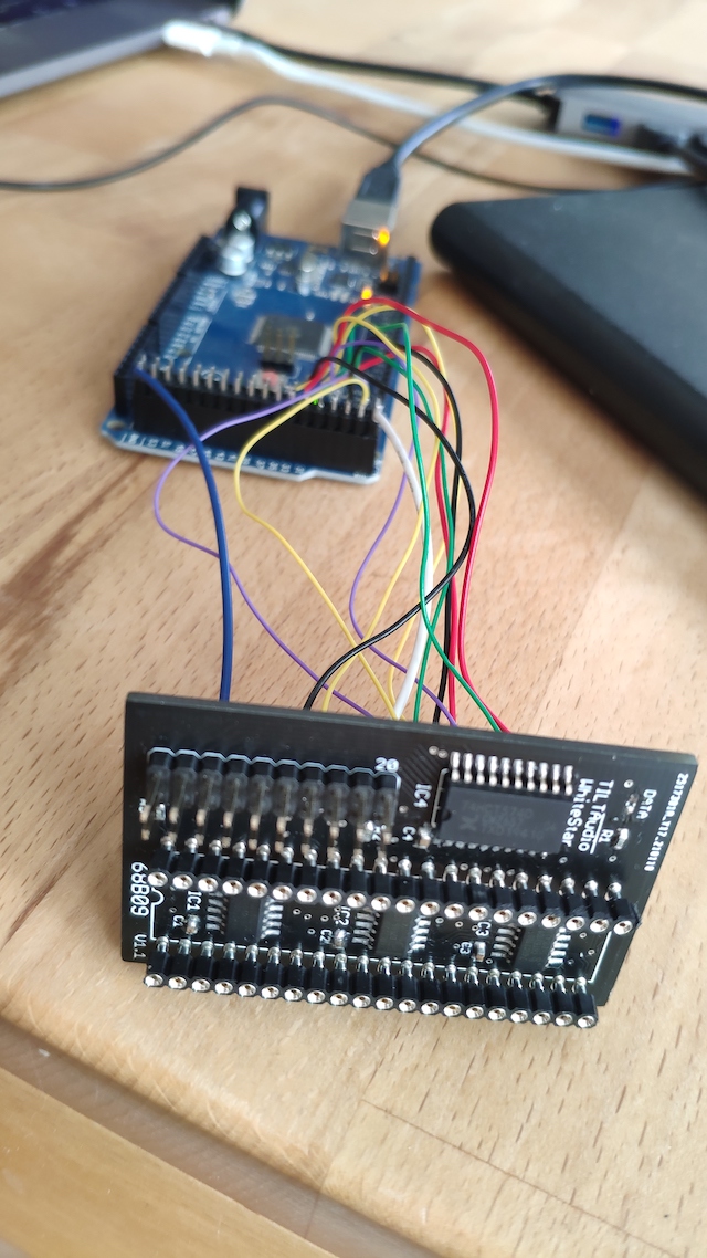
To simulate a cpu writing sound commands we can use an arduino mega, that provides a “8 bit data bus” = PORT A. Two outputs to drive Q and E and one additional output that toggles one of the address bits, e.g. A15. all in all 1 data bit plus common ground / 5V.
All other address bits are just hard wired to high or low to match the required bit pattern for 0x38??.
Pinout Arduino Mega
So using the lower end 2×18 connector we have all we need to connect to a DIP20 socket that the whitestar adapter is plugged in.
Full schematic for WS adapter
Looking at the schematic, one can easily see that the falling edge of “Q” will latch the data and the rising edge of “E” will trigger the “strobe” (also rising) on the data bus to data east.
Of course this will only happen if the address decoder detects a 0x38 for A8-A15 on the address bus.
Based on this I created a small sketch for the arduino mega (see … ) that sends a few bytes in a loop, which should result in some sounds on the TILT!Audio board.