
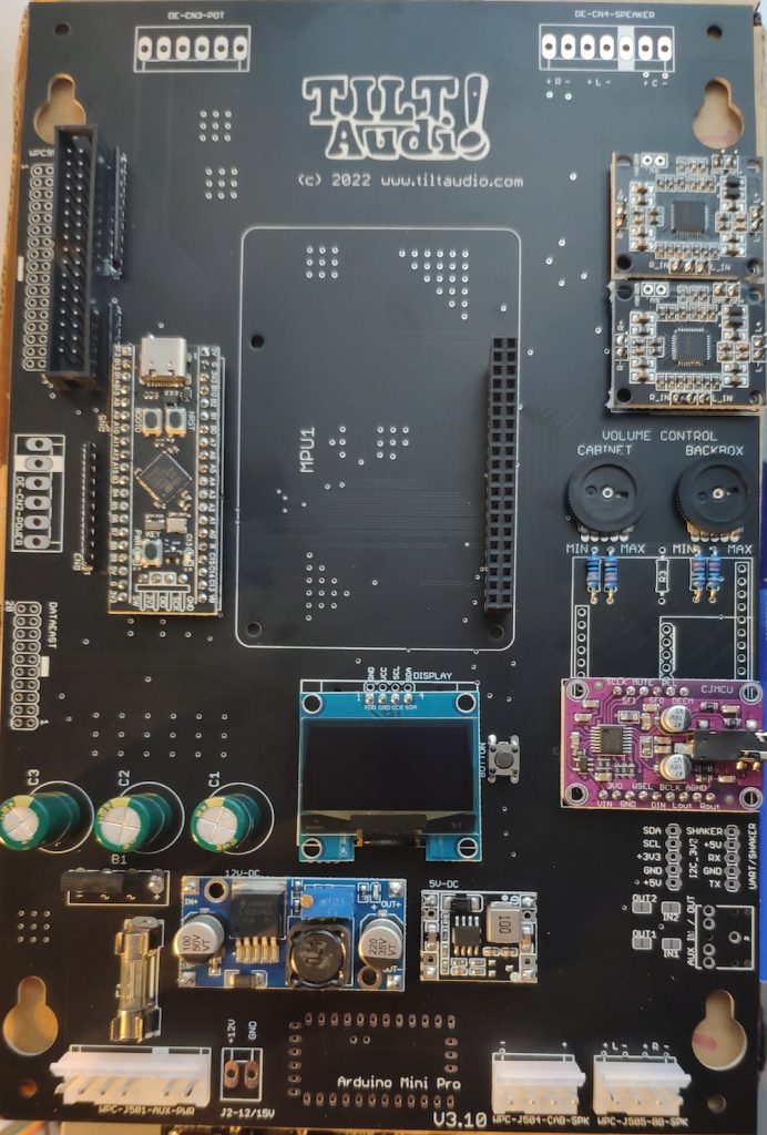
Latest Rev 3.10
The latest board rev 3.10 features a optional arduino pro mini and the board is slimmer, so it can be mounted easier in non DCS machines. More details see assembling rev 3.10 post
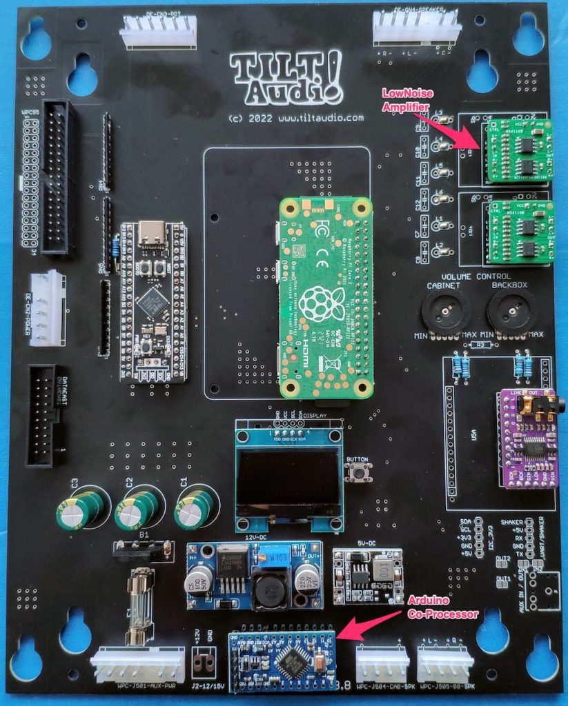
Rev 3.8
See rev. 3.8 post to learn about the new option to add an arduino directly to the board to control an extension like leds or shaker.
Rev 3.5 / 3.6
See what’s new post for 3.5. In general 3.5 and newer is easier to assemble as it has less parts and no smd soldering required any more.
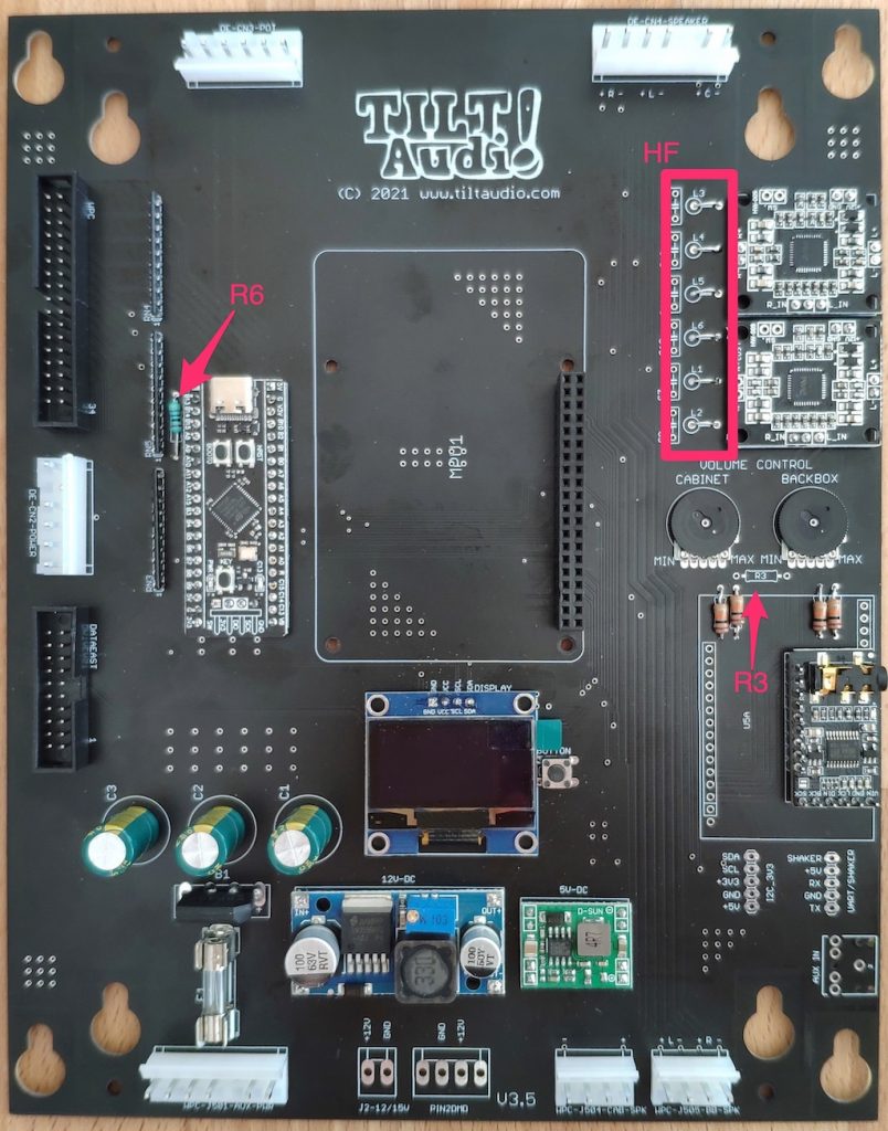
Notes:
- R3 should be left out if no DSP is used.
- R6 is new (next to the stm board) must be 1k
- HF filtering next to the amps is optional, so L1-L6 need wire bridges oder solder bridges
- The STM daughter board has 4 extra pins at the lower end. These need to be connected as well otherwise the flashing of the stm will fail.
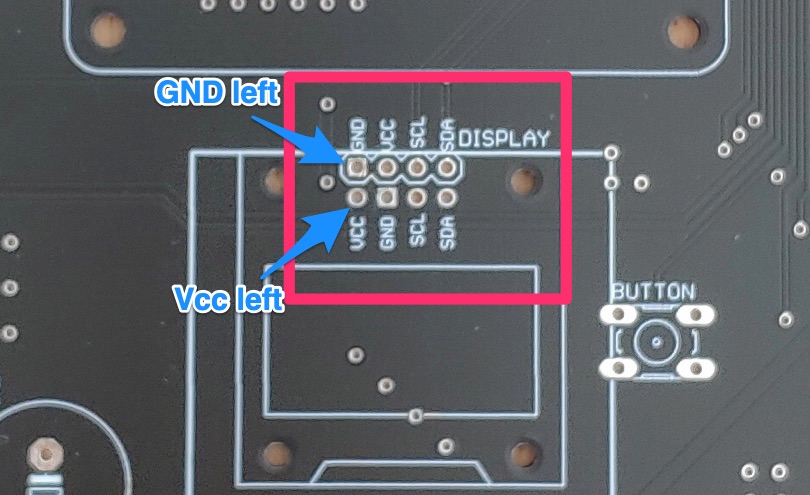
- Take care when connecting the OLED: there’s 2 possibilities depending on the type of OLED. Some have Gnd on the left, some Vcc. Please double check, that you are using the right slot.
There is also an excellent wiki from Charlie in the US, that helps with assembling the kits: https://www.slapsavecreations.com/tiltaudio
Another source for how to build and install TILT!Audio is Craigs great video documentation
Rev 2.8 / 3.0
If you have a new board rev 2.8 or 3.0 see this extra post. Other hints and tipps on this page are deprecated and refer to older revisions.
In case you got a OLED display with reversed Gnd/Vdd connector see here.
XSMT on DAC module
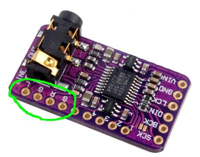
Up to board rev 2.5f there’s a bug with the XSMT connection of the DAC module. XSMT controls the soft mute, if you solder the pin you’re muting the DAC -> no sound. This is fixed in newer releases. Most people anyway solder only L G R G
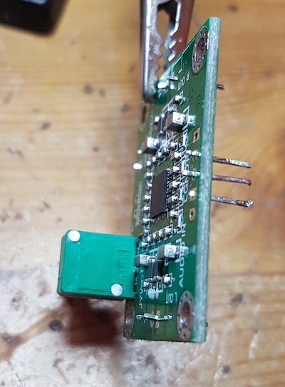
Latest amp modules
Latest amplifier modules from china unfortunately have a slightly different pinout (see picture). This means you need to use wires instead of header pins to connect speaker outputs.
FAQ:
- Most frequently asked: why is the xxx missing?
- The boards are designed to have different options. Depending on options, not all the pieces are necessary. Especially if you choose to use it e.g. data east only, you don’t need the power supply part for WPC.
- Also for WPC power there’s two options: 1. DC-step down or linear regulator with heat sink. The actual board design has both, but you need to apply only one. Maybe I will remove the linear regulator option with the next release, I just wasn’t sure in the beginning which would be the better option.
- What does the colored dots or crosses on the PCB mean?
- Does not need to be populated for this option.
How to solder the SMD chips
As some people hesitate to build such a kit, because it includes soldering some smd chips, I did a short video, that shows how easy it is. Its uncut and really takes only 5 min to do it:
Revision 2.5d (red)
Not much to say about the new revision 2.5d (red). Basically fixed the flaws of the green board. Still there are two either or power supply solutions for WPC:
- DCDC-Step Down converter.
- Linear reg. 7815 with heatsink
Depending on what is available (and works best) I will provide one or the other with the kits.
Red board for DataEast only:
- no power supply (DataEast just using builtin)
- only connectors required for DataEast / Sega
Replace a wpc sound board
see replace TILT!Audio board on a wpc
Revision 2.5c (green)
see assembly-instructions-for-2-5c-green
Revision 2.5a
see here 2.5 blue board
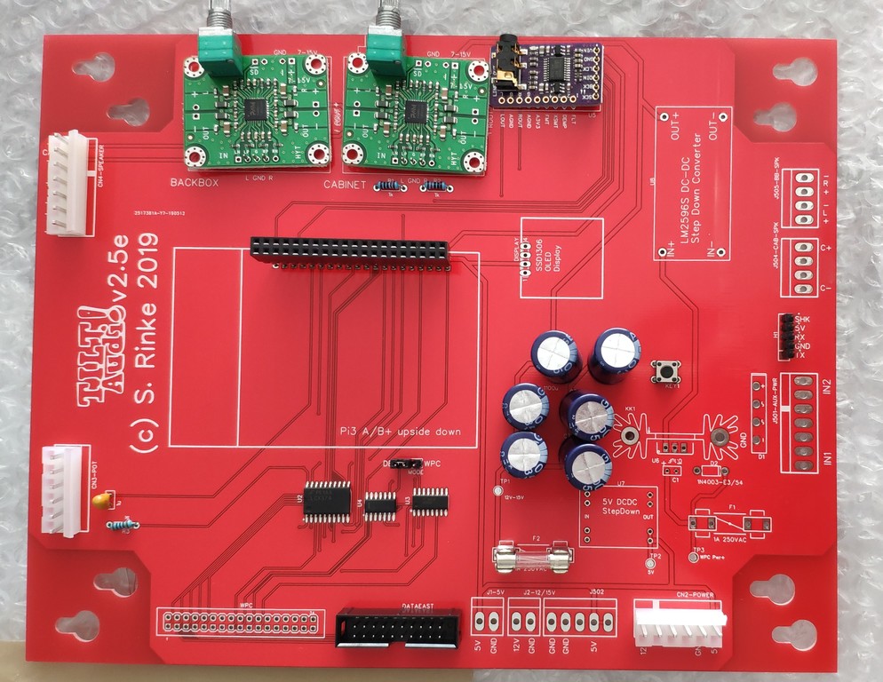
Revision 2.2
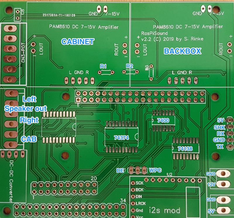
Pictures “says” more than 1000 words …
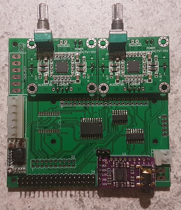
Note: this is a Zero-Revision release and therefore has some flaws (sorry for that). If you follow my advice it should be no problem to deal with that.
- Be aware of the orientation of the big smd piece LCX374. Its pin 1 is on upper right.
- The i2s module (purple) does not fit exactly, first solder the 6 pins on the left, then connect the two output (L and R) with a small piece of wire. This will be corrected in the new revision.
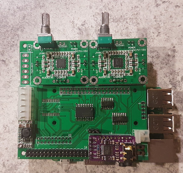
- For Pi3 underneath mounting there is a chance that the Pi’s ethernet connector touches the shield and maybe causing a short even so there should be enough solder resist to prevent that. To be save, just put something in between and fix it with some glue.
- If you like to use a PiZero the Pi connector on the shield must be mounted on the top.
Power supply is only on the 12V in connector. The Pi itself is driven by the onboard dc-dc step down converter, that produces 5V. The 5V connector bottom right can either be used as an 5V outlet (converter makes up to 3A) or simply don’t populate it at all.
As an alternative you can leave out the step down converter and instead provide 5V via the connector bottom right.
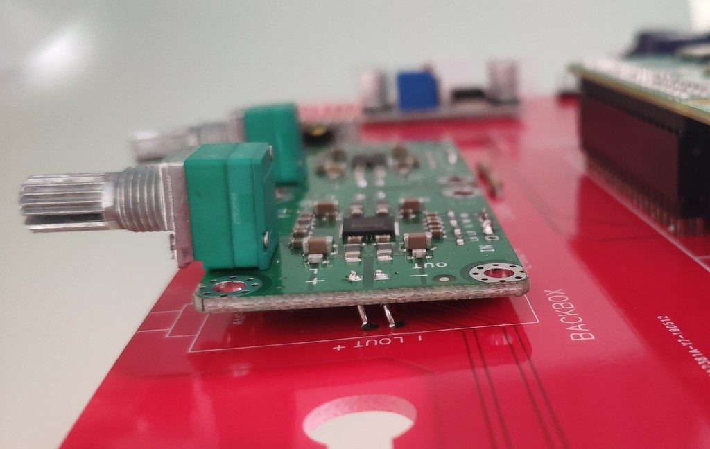
Amplifiers with “connectors”
Sometimes its not easy to get the amplifier modules without connectors like these:
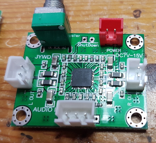
In order to prepare these for mounting you just need to pull of the white and red plastic cases:
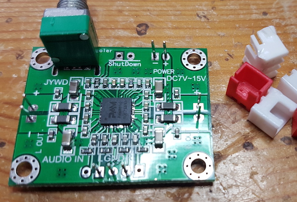
Finally use your soldering iron to heat the pin from the bottom and the push the pin to the other side (bottom side) like this:
Prepared this way it is easy to put them onto the main pcb with original pins as mounting pins through the provided holes.