The latest board has a slightly slimmer layout and the wider DCS like mounting holes can be removed. Also the mostly unused HF output filter for the amps were removed, so no more soldering bridges here.
This assembly post features a multi image step by step build up. So it should be easy to follow for everyone.
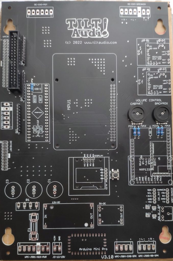
First solder the flat components like resistors, resistor networks, pots, idc connectors …
flat components first
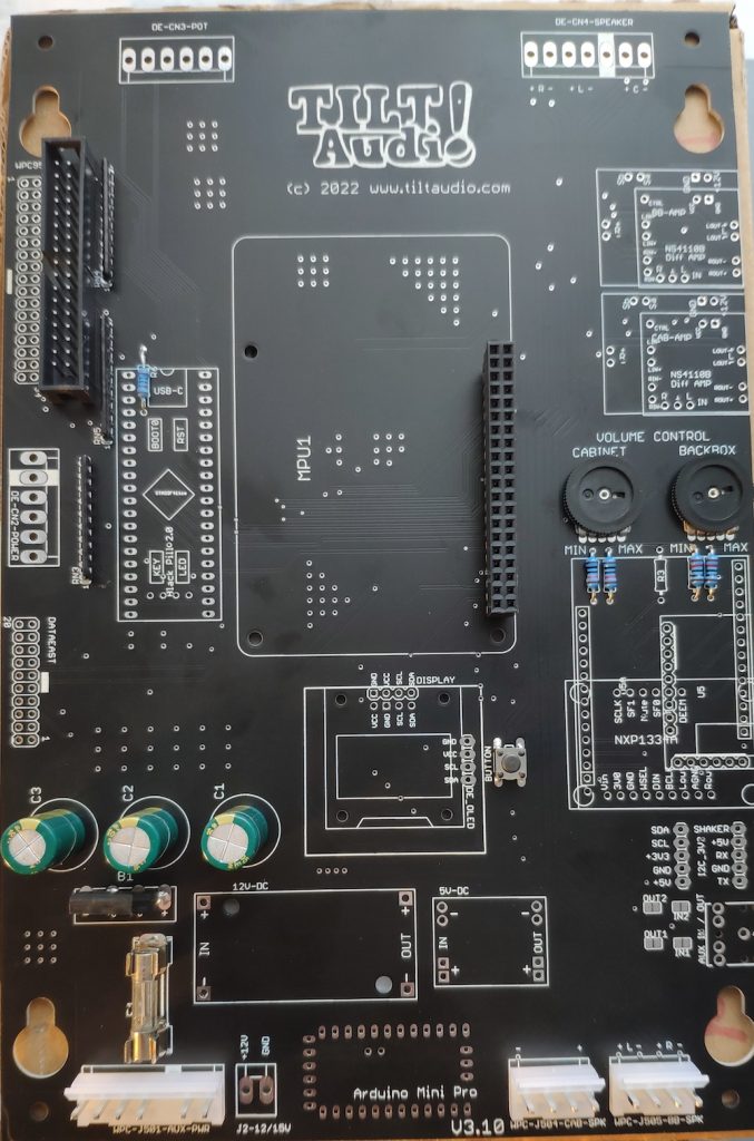
Second add higher connector for the pi and molex connectors for the game, passive power supply parts: rectifier, caps, fuse …
higher connectors & passive comp. added
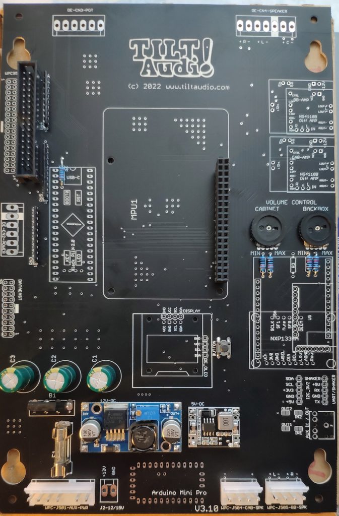
Then add the two DC DC converter modules
only power supply modules added
At this time you could (and maybe should) check the power supplies. So far no consumer is mounted, so connecting the J501 to the game (or left most & right most pin to a regulated power supply) should do no harm.
If all works well, you should have 12V on the amp power supply (upper right) and 5V e.g. on the connector right.
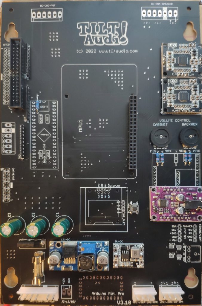
DAC module & amps added
Now with DAC module and amp modules added, you could do a test with the PI applied already. Everything should work, but of course only with sounds triggered from the webUI. This test could also be skipped.
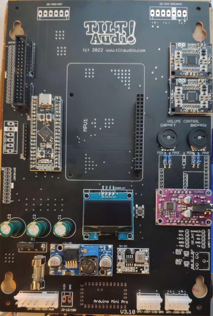
Fully populated for wpc
Last step is added the stm (black pill) submodule and the OLED (optional, but recommended). Now with the PI attached, you should be ready to go.
This adapter simply decodes parts of the 6809 address bus: A8 – A15. More fine grained decoding is not necessary as the peripheral address mapping is done by the upper 8 bit only.
So write access to 0b00111000???????? = 0x38?? will be recognized as a sound command.
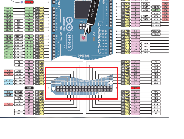
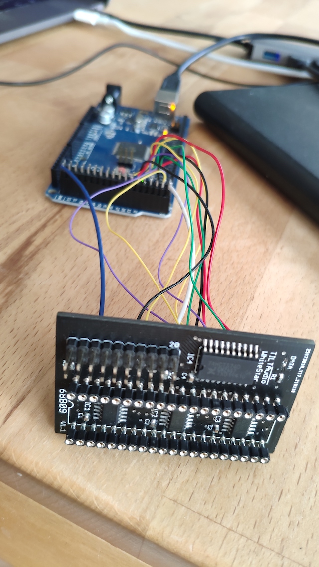
To simulate a cpu writing sound commands we can use an arduino mega, that provides a “8 bit data bus” = PORT A. Two outputs to drive Q and E and one additional output that toggles one of the address bits, e.g. A15. all in all 1 data bit plus common ground / 5V.
All other address bits are just hard wired to high or low to match the required bit pattern for 0x38??.
Pinout Arduino Mega
So using the lower end 2×18 connector we have all we need to connect to a DIP20 socket that the whitestar adapter is plugged in.
Full schematic for WS adapter
Looking at the schematic, one can easily see that the falling edge of “Q” will latch the data and the rising edge of “E” will trigger the “strobe” (also rising) on the data bus to data east.
Of course this will only happen if the address decoder detects a 0x38 for A8-A15 on the address bus.
Based on this I created a small sketch for the arduino mega (see … ) that sends a few bytes in a loop, which should result in some sounds on the TILT!Audio board.