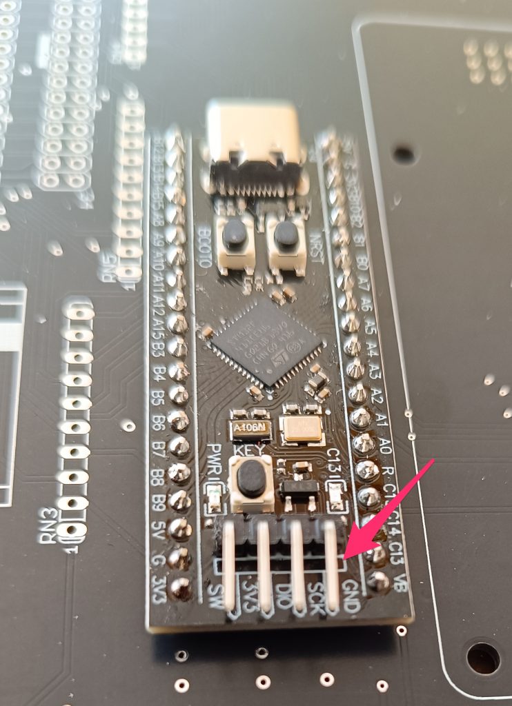
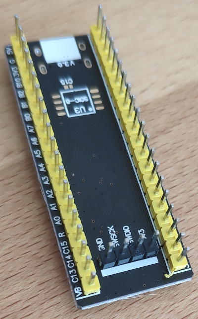
When you got a delivery where the STM modules are already populated with headers like in the 1. picture, you still need to connect the 4 extra pins in order to get the STM flashed correctly. With the attached header (see arrow), that does not work.
So you either add 4 wires then need to be soldered on the pcb first and connect them to the header or you add an additional 4 pin header on the lower side of the STM module that then connects to the 4 holes on the main pcb.
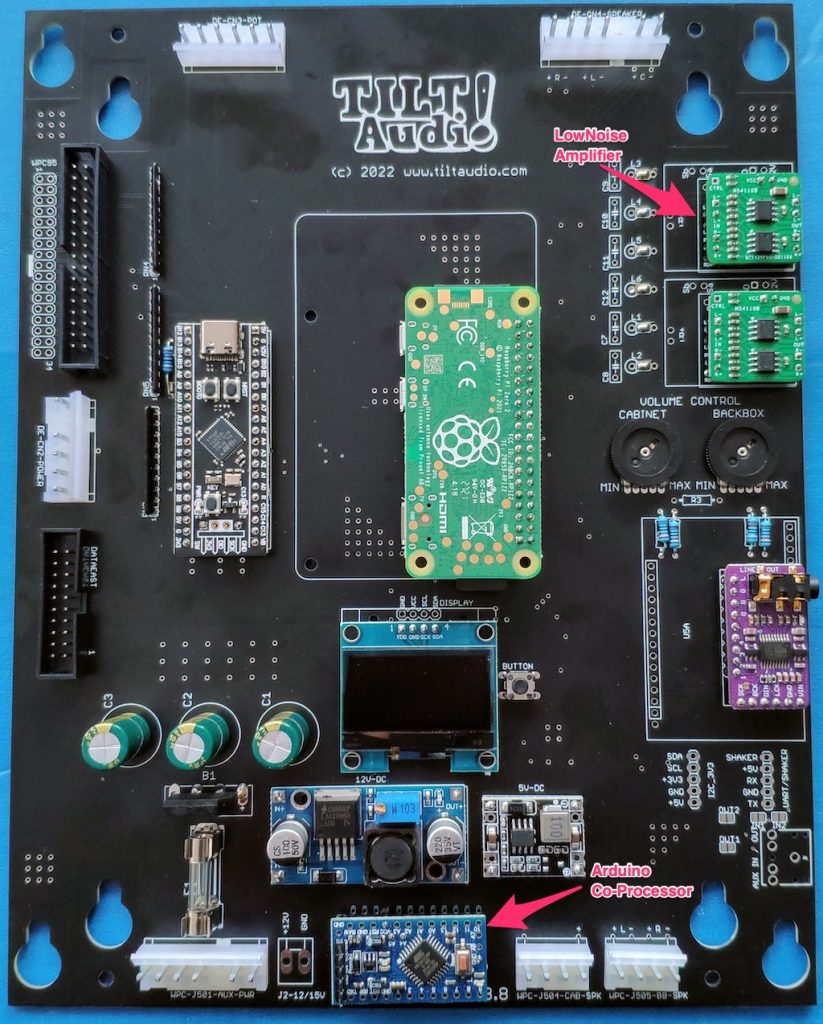
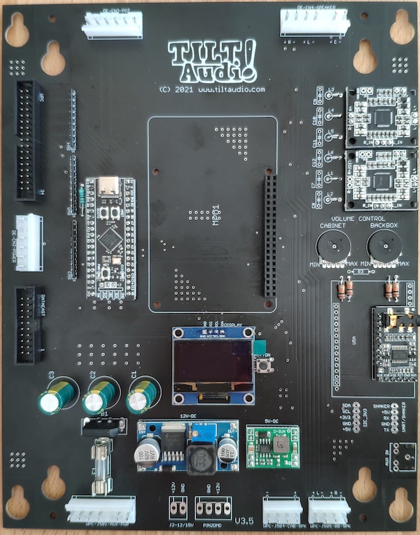
The new board rev comes with a dedicated place for a co-processor (arduino mini pro) to control various extension.
Fully assembled it looks like this
Fully assembled rev 3.8 board with arduino mini pro as co-processor and low noise amps
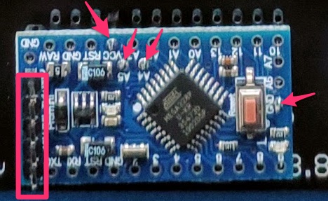
Arduino attached with 4 pins minimal, plus programming header
The arduino is connected with minimal 4 pins: Vcc, Gnd, SDA, SCL. Also the UART (RX,TX,Vcc,GND) on the left side has a header attached for programming. You can program the arduino “on board” but you either need to power the 5V from the machine and connect only TX, RX and Gnd or you also connect Vcc from the programming adapter (USB-to-Serial TTL) but then you need to disconnect the power from the board and also better remove the raspberry pi (board will be supplied by 5V from the adapter, which is okay for STM and DAC, but PI would be to much).
The most important change since the latest release: the annoying “sound interface error” with some WPC machines (TAF, STTNG, …) is now gone!
The old discrete decoder hardware build based on 3 smd logic chips was replaced by a STM32F4 micro controller module. This way the micro controller can talk to the game, avoiding the “sound interface error” and also takes over the command decoding.
There some more advantages with this new design:
no more jumper. Data east input or wpc input is recognized automatically
no more smd soldering. The new mcu module is normal through hole.
no need for analog digital converter (for old style data east pot). The STM32 takes over this task as well.
no need for pull up resistors networks. The STM32 has internal pull ups.
no decoupling caps for smd needed.
All in all there are 10 pieces less to solder and replaced by one STM32 module (plus one resistor).
Other improvements
Additionally there is an extended connector for the OLED display (was already on rev 3.1) that can be used with both types of OLEDs (either GND left or Vcc left). Depending on your OLED type you need to use the upper or lower row to connect.
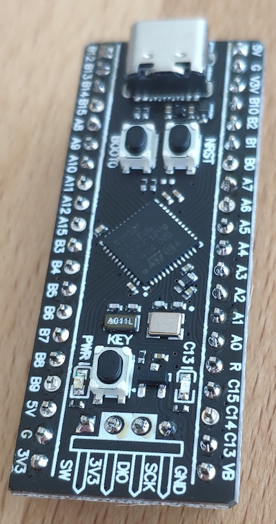
MCU with soldered headers
STM32F4 module
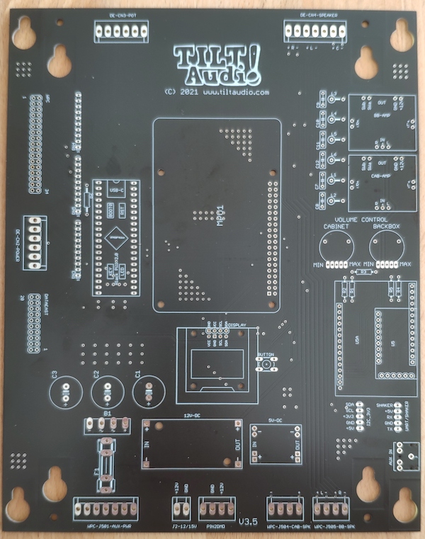
Bare rev 3.5 baord
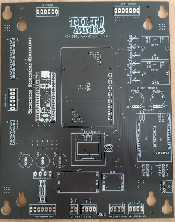
Rev 3.5 with STM32F4
Totally assembled for DE&WPC
More changes
The HF filtering at the amplifier outputs are now optional. Only a very few user were ever effected by that. So you could still assemble the 6 impedance filter and caps if you like, but the parts will no longer be included in the kits. Instead you need to bridge the L1 – L6 with a wire (or solder jumper).