A few notes on the assembly of the latest boards rev 2.8 and 3.0
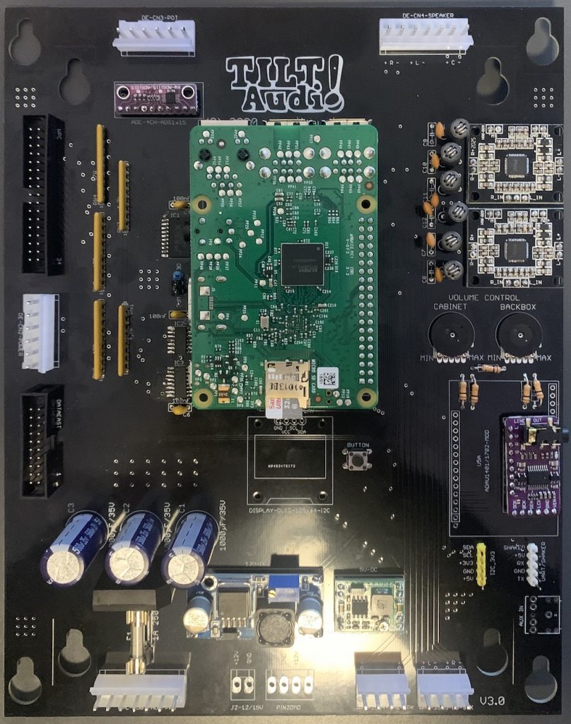
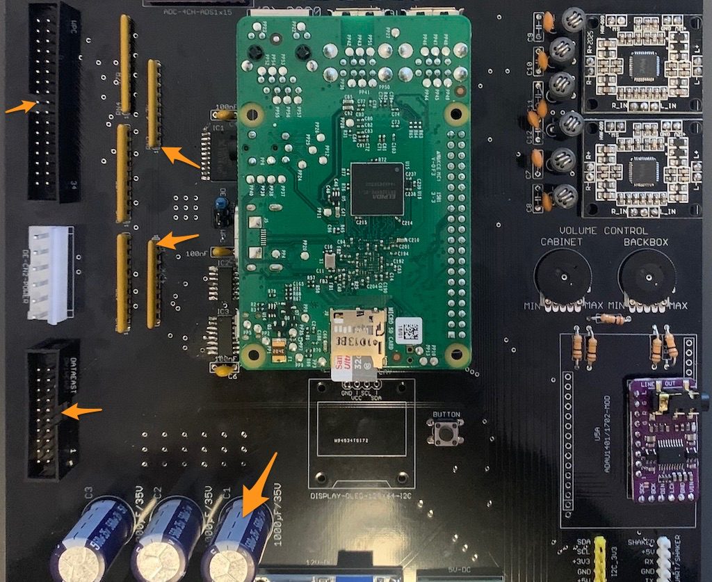
The picture shows a fully populated board for both data east and WPC.
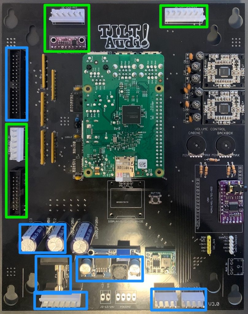
Same picture but highlighted in green what is data east (whitestar) only, highlighted in blue what is wpc only.
From the label on the PBC it should be clear, how to mount the parts. But for some there is different orientation possible or it is not clear where to place pin1.
Resistor networks / pin headers
RN1 / RN2: these are resistor networks used as pull up so there is a pin1 connected to 5v.
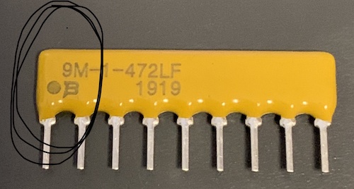
Resistor network pin1 marking must match the orange arrows see picture below.
If you use double row header with polarization slot, be sure it point to the right direction (34 to edge of pcb, 20 to inner pcb, see arrows
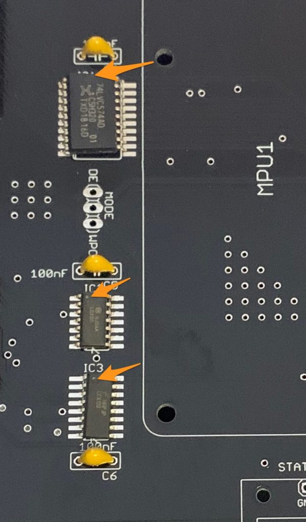
E-CAPS / SMD
Also note the gnd side (upper side in this picture) for the e-caps.
Last but not least the smd ICs all have their pin1 upper left. You will notice the small dot in the upper left corner (resp the notch for the 574)
DC DC converters
The dc dc power converter modules are sometimes with fixed voltage 12v / 5v sometimes adjustable. If you got the adjustable one, don’t worry I have already adjusted them to 5v or 12v resp. So no need to do anything on your side. If you accidentally push one of the trimmers, you need to carefully readjust to 5v or 12v to not risk to fry the raspberry pi or the amplifiers.
Optional OLED
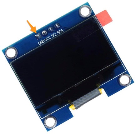
One more comment on the OLED display: you can always add one on your own if you did not include one in your order in the first place. Two type are supported: 0.96” with SSD1306 controller and 1.3” with SH1106 controller. Just be sure that you buy one with the power connectors starting with Gnd, Vcc, … from left to right. I’m mentioning this because you get different ones as well. Best fit would be for example: https://www.amazon.de/DollaTek-seriell-SSH1106-Display-LCD-Modul/dp/B07QJW9FHJ. It has the Gnd connector on the left, so it will work fine.
Speaker WIRING for WPC (old mono)
Old wpc games only have a mono sound with 3 speakers wired like this:
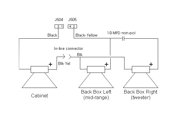
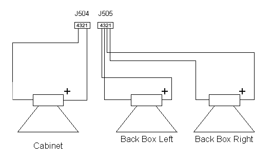
With TILT!Audio you get full stereo plus sub woofer channel for the cabinet speaker (2.1 sound). Therefore the speaker wiring needs to change:
As the backbox right speaker in such games is only a tweeter, I would strongly recommend to also exchange speakers in the backbox.
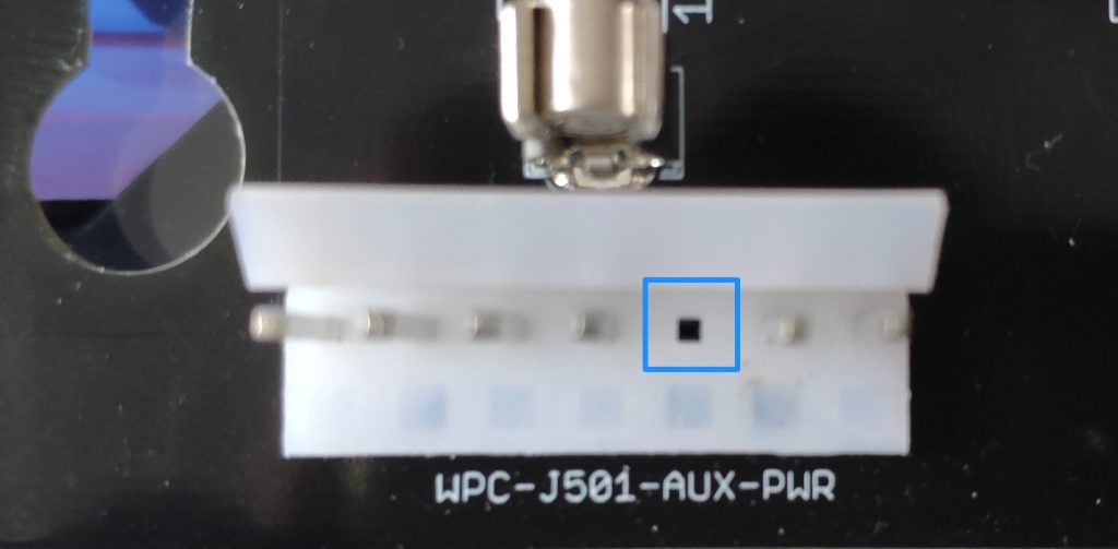
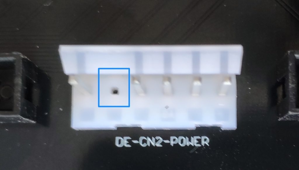
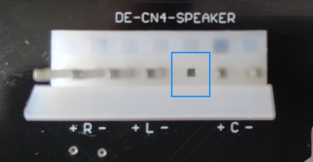
KEYPINS molex connectors
3 of the molex connectors have a key pin (a pin that needs to be removed). It is easy to remove it before soldering. See images below which pin to remove:
GENERAL
Some general advice and hints:
- dc dc converters must have the correct orientation (see picture above)
- the raspberry pi header need some distance to leave enough room for a pi3 with all its USB / network connectors
Images courtesy of Mike L. Very much appreciated.