
In order to test your TILTAudio board including the WPC bus interface to the pinball machine you can use an arduino mega board.
Just connect the mega with the TILT!Audio board like this:
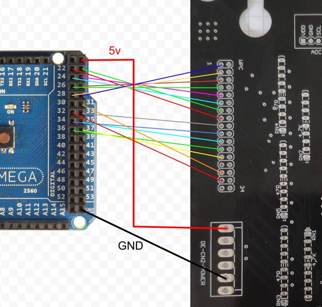
Connecting also the 5v power line is optional. You need to choose either to power everything from on source or just skip the red 5v wire and power the 5v on the TA board and the Arduino separately.
For the address decoder (the smd chips) to work the raspberry pi needs to be plugged in as the 3v3 power for the decoder comes from the pi’s onboard regulator.
Also the resistor network RN3-5 must be installed, without them bus connections are not there. 12V can be skipped for testing, which means amps will not work, but you could also connect a speaker either to the PI’s audio jack directly or use the audio jack on the DAC module.
Then load the following ino script to the Arduino:
|
1 2 3 4 5 6 7 8 9 10 11 12 13 14 15 16 17 18 19 20 21 22 23 24 25 26 27 28 29 30 31 32 33 34 35 |
void setup() { // set gpio mode DDRC = 255; // switch port c completely to output DDRA = 255; // switch port a completely to output PORTA = 255; // high PORTC = 255; // high pinMode(LED_BUILTIN, OUTPUT); } int data[] = { 0x01, 0x20, 0, 0 }; int ledState = 0; void play(int start, int end ) { for( int i = start; i <= end; i++ ) { delayMicroseconds(900); PORTA = data[i]; PORTC = 0b01011100; // sound address + rw = low, with wden high delayMicroseconds(20); PORTC = 0b00011100; // sound address + rw = low, with wden low delayMicroseconds(30); PORTC = 0b01011100; // sound address + rw = low, with wden high } } void toggleLed() { digitalWrite(LED_BUILTIN, ledState); ledState = !ledState; } void loop() { play(0,1); delay(2000); toggleLed(); data[2] = random(4); data[3] = random(256); play(2,3); delay(4000); } |
This way you can emulate sound effect commands to would normally come from the pinball machine.
I will upload a more detailed example on the github repo: https://github.com/sker65/tiltaudio-extensions
Connections needed:
| Arduino | TILT!Audio |
| PA0:22 | CD0 wpc15 |
| PA1:23 | CD1 wpc13 |
| PA2:24 | CD2 wpc11 |
| PA3:25 | CD3 wpc9 |
| PA4:26 | CD4 wpc7 |
| PA5:27 | CD5 wpc5 |
| PA6:28 | CD6 wpc3 |
| PA7:29 | CD7 wpc1 |
| PC0:37 | CA0 wpc25 |
| PC1:36 | CA1 wpc23 |
| PC2:35 | CA2 wpc21 |
| PC3:34 | CA3 wpc19 |
| PC4:33 | CA4 wpc17 |
| PC5:32 | RW:wpc31 |
| PC6:31 | WDEN:wpc29 |
| GND | GND |