Using a Arduino mini pro as extension to a TILT!Audio board, you can easily control a shaker motor via pwm (pulse width modulation).
First we need a motor driver module that is capable of driving the high current motor power. e.g. something like this:
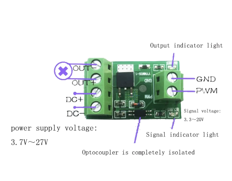
The picture is more or less self-explaining the only thing that need to be connected to the Arduino mini pro is the GND / PWM input.
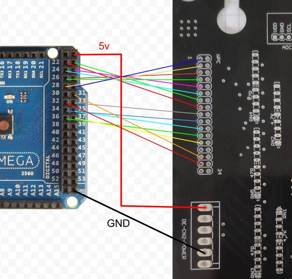
Now looking at the Arduino mini pro we use pin 5 as pwm output and to connect to the TILT!Audio board we use the i2c bus the is controlled by the SCL / SDC pins (together with GND / Vcc of course):
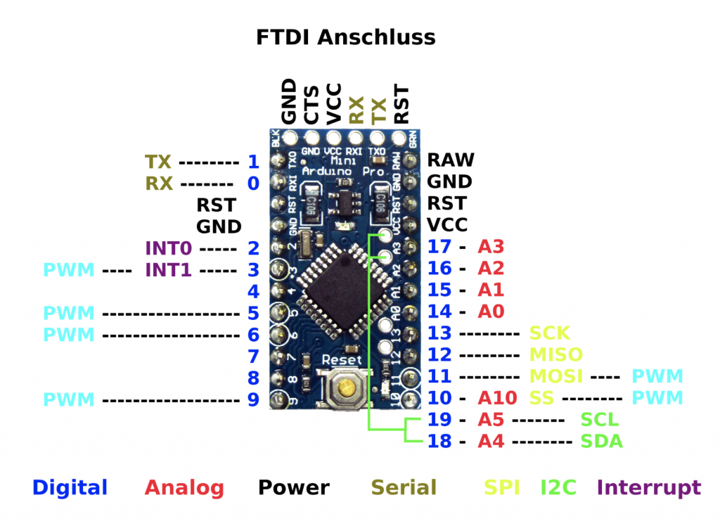
Be sure to choose a 5v type for Arduino mini pro as there are also available in 3.3v but the TILT!Audio connector for the i2c bus provides 5v. Also the 5v type runs on 16Mhz instead of only 8Mhz for 3.3v with is also good.
So connections are:
| From | To |
| TA-Board: GND | GND (right side) |
| TA-Board: Vcc | VCC (right side) |
| TA-Board: SDA | SDA (green) |
| TA-Board: SCL | SCL (green) |
| Arduino: GND | Power Driver: GND (right) |
| Arduino: Pin5 (PWM) | Power Driver: PWM (right) |
Now we create a script for the Arduino mini pro like this (see https://github.com/sker65/tiltaudio-extensions). We start with initial setup stuff:
|
1 2 3 4 5 6 7 8 9 10 11 12 13 14 15 |
#include <Wire.h> #define I2C_MSG_IN_SIZE 2 #define I2C_MSG_OUT_SIZE 4 #define I2C_ADDRESS 0x61 #define PWM_PIN 5 void setup() { // init i2c bus Wire.begin(I2C_ADDRESS); Wire.onReceive(receiveEvent); // not used Wire.onRequest(requestEvent); // init PWN output pinMode(PWM_PIN, OUTPUT); } |
First thing we do is switch shaker on, off and set speed (within a limited range to not make to pinball machine jump):
|
1 2 3 4 5 6 7 8 9 10 11 12 13 14 15 16 17 |
int currentSpeed = 1; int maxSpeed = 20; void off() { analogWrite( PWM_PIN, 0 ); } void on() { analogWrite( PWM_PIN, currentSpeed ); } void setSpeed( int speed ) { if( speed > 0 && speed <= maxSpeed ) { currentSpeed = speed; } on(); } |
Second we wire these functions to i2c control:
|
1 2 3 4 5 6 7 8 9 10 11 12 13 14 15 16 17 18 19 20 21 |
void receiveEvent(int count) { if (count == I2C_MSG_IN_SIZE) { byte cmd = Wire.read(); byte value = Wire.read(); switch( cmd ) { case 0x01: on(); break; case 0x02: off(); break; case 0x03: setSpeed(value); break; default: // unknown command } } } |
And additionally we can create “sequences”. A sequence would play back some schema of on and off or speed up and speed downs. The idea is to define a sequence as 3 integers: command byte, value, interval in milliseconds. We define these commands:
- 0x00: stop -> end of the sequence
- 0x01: switch on, value -> speed
- 0x02: switch off, value -> don’t matter
- 0x03: ramp up, value -> target speed at end of interval
We delegate playing those sequences to the Arduino and later just trigger it from the TILT!Audio board by sending some command to the i2c bus:
|
1 2 3 4 5 6 7 8 9 10 11 12 13 14 15 16 17 18 19 20 21 22 23 24 25 26 27 28 29 30 31 32 33 34 35 36 37 38 39 40 41 42 43 44 45 |
#define END 0x00 #define ON 0x01 #define OFF 0x02 #define RAMP 0x03 #define SETSPEED 0x04 #define PLAYSEQ 0x05 int sequences[] = { ON, 5, 500, OFF, 0, 500, ON, 5, 500, END }; int* seqPtr = NULL; unsigned long nextAction = 0; // timer marker for next action float rampInc; // speed incs for ramps in steps int rampNo = 0; // counts number of step in ramp phase void loop() { unsigned long now = millis(); if( now > nextAction ) { // ramp active if( rampNo > 0 ) { nextAction = now + 50; setSpeed( currentSpeed + rampInc ); rampNo--; } else { // read next command from sequence int cmd = *seqPtr++; if( cmd == END ) { seqPtr = NULL; // end of sequence nextAction = 0; } else { int val = *seqPtr++; int delay = *seqPtr++; nextAction = now + delay; switch(cmd) { case ON: setSpeed(val); break; case OFF: off(); break; case RAMP: rampNo = delay / 50; // inc every 50ms nextAction = now + 50; rampInc = (val - currentSpeed) / (float) rampNo; } } } } } |
And again create a function that triggers the sequence playback and wire it to i2c control:
|
1 2 3 4 5 6 7 8 9 10 11 12 |
void playSequence( int startIndex ) { if( startIndex >= 0 && startIndex < sizeOfSequences ) { seqIdx = startIndex; nextAction = millis(); } } // add another case in receiveEvent case PLAYSEQ: playSequence(value); break; |
Find the complete example on github.
To get an idea, how it finally will play all together I did a test installation: