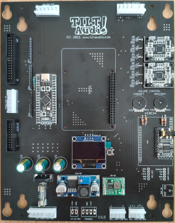
Whitestar Test Modul

This adapter simply decodes parts of the 6809 address bus: A8 – A15. More fine grained decoding is not necessary as the peripheral address mapping is done by the upper 8 bit only.

So write access to 0b00111000???????? = 0x38?? will be recognized as a sound command.

Looking at the bus timing of the 6809 see https://github.com/cavnex/mc6809/blob/master/documentation/6809Details.md the data bus is latched on the adapter with the falling edge of Q, and written (strobed) to the data east compatible connect STB pin with the rising edge of E.

That is basically all the whitestar adapter does.

To simulate a cpu writing sound commands we can use an arduino mega, that provides a “8 bit data bus”  = PORT A. Two outputs to drive Q and E and one additional output that toggles one of the address bits, e.g. A15. all in all 1 data bit plus common ground / 5V.

All other address bits are just hard wired to high or low to match the required bit pattern for 0x38??.

Pinout Arduino Mega

So using the lower end 2×18 connector we have all we need to connect to a DIP20 socket that the whitestar adapter is plugged in.

Full schematic for WS adapter

Looking at the schematic, one can easily see that the falling edge of “Q” will latch the data and the rising edge of “E” will trigger the “strobe” (also rising) on the data bus to data east.

Of course this will only happen if the address decoder detects a 0x38 for A8-A15 on the address bus.

Based on this I created a small sketch for the arduino mega (see … ) that sends a few bytes in a loop, which should result in some sounds on the TILT!Audio board.

Code snippet:

The test adapter looks like this:

Full source code of the sketch can be found at https://github.com/sker65/Whitestar-Tester

Lua scripting with modules

TILT!Audio features a lua runtime 5.2 to control additional extensions like shakers, LED-lights and also servos.

To make this possible TILT!Audio firmware embeds a lua runtime (lua virtual machine) and loads a “init.lua” script from the sound directory.

The init.lua script already has access to all core lua language features and also the TILT!Audio bindings see lua reference. The binding allows access to the sound engine, communicate via i2c, logging messages and get information about the current installation.

Lua in its language ecosystem also offers modules and package managers that allows installing and managing modules that extend lua features. One of this package managers is luarocks.

Luarocks

Using luarocks as package manager to install a new module together with TILT!Audio is not so straight forward as you can read it on most websites, because the linux running on a TILT!Audio card is tailored down to a minimum to run as efficient as it should to produce sound and nothing else.

What is missing for example is a c compiler that most lua modules require as they come as a combination of lua code and c code.

Also luarocks requires a certain directory structure that is aware of the different lua versions and different places in the system where the lua runtime should look for “modules” (which is *.so and *.lua files).

The TILT!Audio start script does set the required environment variables to let lua runtime find modules, but still not in that way that a module installed by luarocks would expect.

Continue reading “Lua scripting with modules”

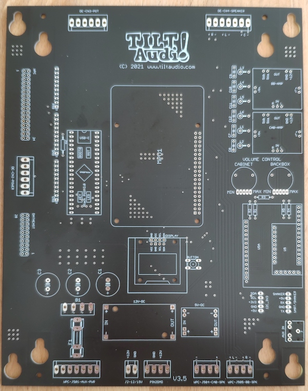
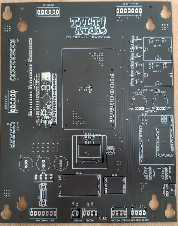
New Revision 3.5 – 3.7

What’s new

The most important change since the latest release: the annoying “sound interface error” with some WPC machines (TAF, STTNG, …) is now gone!

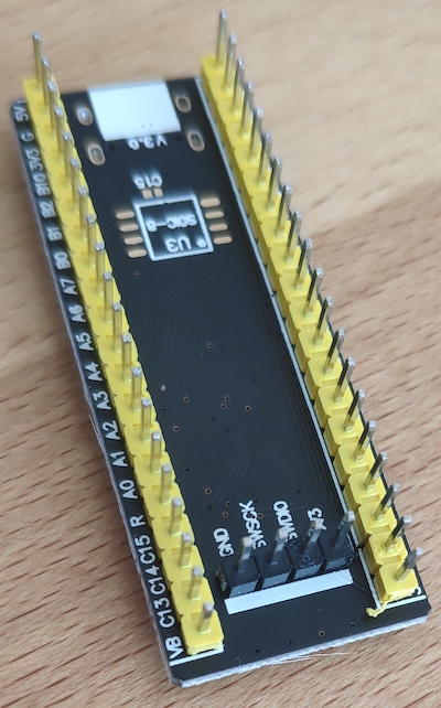
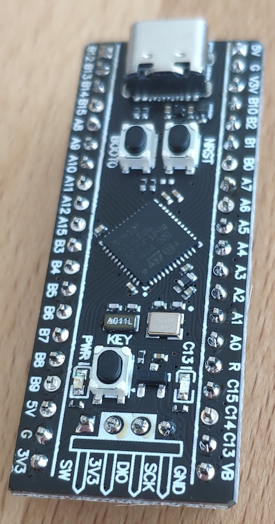
The old discrete decoder hardware build based on 3 smd logic chips was replaced by a STM32F4 micro controller module. This way the micro controller can talk to the game, avoiding the “sound interface error” and also takes over the command decoding.

There some more advantages with this new design:

  • no more jumper. Data east input or wpc input is recognized automatically
  • no more smd soldering. The new mcu module is normal through hole.
  • no need for analog digital converter (for old style data east pot). The STM32 takes over this task as well.
  • no need for pull up resistors networks. The STM32 has internal pull ups.
  • no decoupling caps for smd needed.

All in all there are 10 pieces less to solder and replaced by one STM32 module (plus one resistor).

Other improvements

Additionally there is an extended connector for the OLED display (was already on rev 3.1) that can be used with both types of OLEDs (either GND left or Vcc left). Depending on your OLED type you need to use the upper or lower row to connect.

More changes

The HF filtering at the amplifier outputs are now optional. Only a very few user were ever effected by that. So you could still assemble the 6 impedance filter and caps if you like, but the parts will no longer be included in the kits. Instead you need to bridge the L1 – L6 with a wire (or solder jumper).