
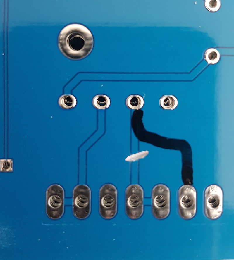
First and foremost the zero series blue boards have a flaw in the layout when used with on board power supply with WPC. There is one wire cut on the bottom near the rectifier and one additional wire needs to be placed. Sorry for that.
When I say elko its “electrolyte capacitors” and when I say right / left its always looking from the top where the logo is readable.
This is the recommended order of soldering components, each of them with some additional hints mostly because of some shortcomings of the zero series.
As a rule of thumb solder small things first, otherwise the big ones get in your way later.
- Solder the smd chips. Check orientation and put some extra fluid on the pcb if you have a fluid pen or something. Put plenty of solder on your iron and just move along the pins. If you create shorts then use some desoldering braid to remove solder again. There’s a couple of video out there with tips and tricks.
- Connectors: devided in 3 sections: Common, WPC only, DataEast only
- Common
- 3 pin header with jumper mode selector (DE / WPC). Place the jumper according to your machine
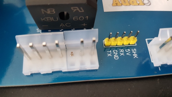
- H1 extension connector (optional) only for shaker / serial media extension
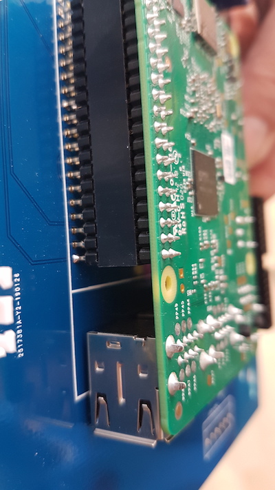
- Raspberry Pi connector: long pin version as you need some space to put a pi3 on the connector upside down. If you have one at hand just try “how high” the connector should be.
- WPC only:
- WPC data connector: looking from the top the notch is left. (pin 1 upper left)
- J504 / J505 WPC speaker connectors
- J501 WPC Aux Power connectors. Sometimes no 7 pin available then use 3+4 pin. Looking from the top 3rd pin from the right is key pin and therefore need to be cut off / pulled out.
- Common
- Resistors: just two resistors (560R to 4K7 exact value doesn’t matter, but equal) near the cabinet amplifier.
- DataEast only: 1K resistor and cap near CN3 for reading cabinet pot.
- 5V DC-DC buck converter module. Looking from the top lower left is “out+” upper left is “in+” in the right “gnd”
- Amplifier moduls: if you have the ones with white and red plastics applied, remove them first and push the pins to the bottom side with heat from the soldering iron. Maybe the pins need some tweaking to make the fit into the whole.
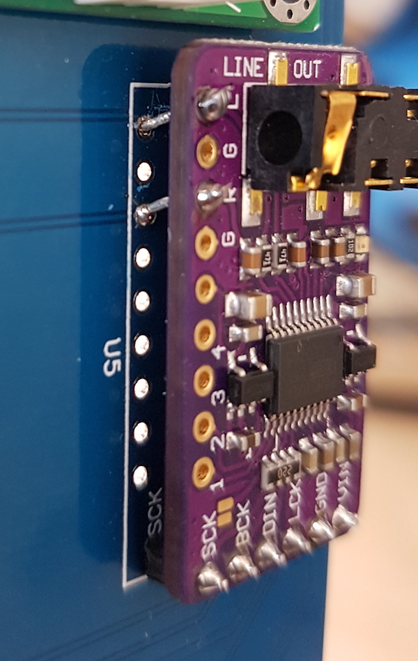
- DAC modul: just use the 6 pin header at the lower end. Looking from the top in the left side you need to connect only 2 wire “L” and “R”. Again zero series flaw the holes underneath do not exactly fit the modul holes, so please use some flexible wire to connect these (will be fixed in the next hardware revision).
- WPC only: on board power supply:
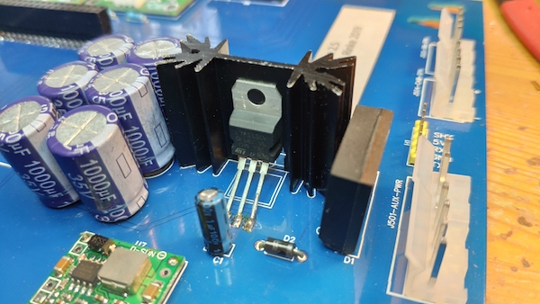
- Again minor zero series flaw: the heatsink is too far on the right so you need to tighten the linear regulator onto the heatsink by soldering not through the holes but only onto the pads (see picture).
- block rectifier. be aware of orientation + side / – side.
- Diode D2 and capacitor C1. If c1 is an elko looking from the top ground is lower hole (near c1 letters)
- Last: 6 big elkos: again small zero series flaw. the elkos
General advice with 3.96” connectors: remove the key pin before soldering! Take a pliers and pull it out. Newer boards have the key pin marked on pcb printing. For olders you need to check the original connector.
After assembly do a step by step test if you have a meter first do some checks without pi applied. Just connect WPC aux power J501 and check voltages:
- after rectifier about 20V
- after linear regulator 15V (depending on reg type maybe 12V)
- after DC DC buck converter 5V
If all is fine prepare sd card image and plugin the pi. If you like to use web ui please setup up your wifi right from the beginning.