I finally took the time this evening and put one of my spare TILT!Audio boards into my msf game. Took only a few minutes to replace and it plays very nice.
My msf has a few more mods like extra leds in backbox speakers, big color pin2dmd and also the whole gi is rgb. But to be honest the biggest thrill is always the new sound. Of course I replaced the speakers as well to get more volume and clearer sound.
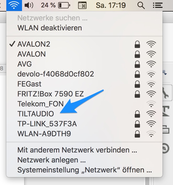
If wifi is not configured in the beginning and TILT!Audio cannot get an IP address it creates it own Wifi hotspot named „TILTAUDIO“. As soon as you see this wifi network appearing on your computer just connect by using the passphrase „tiltaudio“.
If you want to
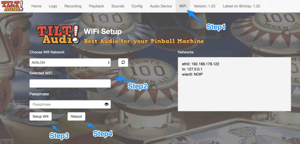
include the TILT!Audio system in your home wifi navigate to „Wifi“.
Choose your wifi network and enter your passphrase, press „Setup
Wifi“ and finally Reboot.
This will reboot the TILT!Audio system and after it is up again, you should reach the web ui by simply http://tiltaudio:31008/ . If this doesn’t work you need to find out the ip address by checking your router for a new device.
10 Band Equalizer
There are a couple of new synthetic audio devices, that add some signal processing before hand over sound to the hifi DAC. One of them is a 1 band equalizer, that allows fine tuning your sound output for TILT!Audio.
You can listen to every sound from your sound set or choose one of the test sounds and then fine tune the sound exactly for your system.
The equalizer is a global fine tuning, that applies the same „curve“ to all sounds from TILT!Audio. Of course it is still possible to add a per sound increase or decrease of volume.
Bugfixes / Changes:
Bugfix when loading altsound sound packs
Change default to enable_i2s to true so it matches all newer shields.
Added option to reboot from web ui as part of wifi setup
Rename low level service to “tiltaudio”. When ssh to pi use “sudo systemctl start/stop tiltaudio” …
Changes storage for “tmp settings” like sound set, volume and audio device to ta.ini file